Posts

Curves

Image
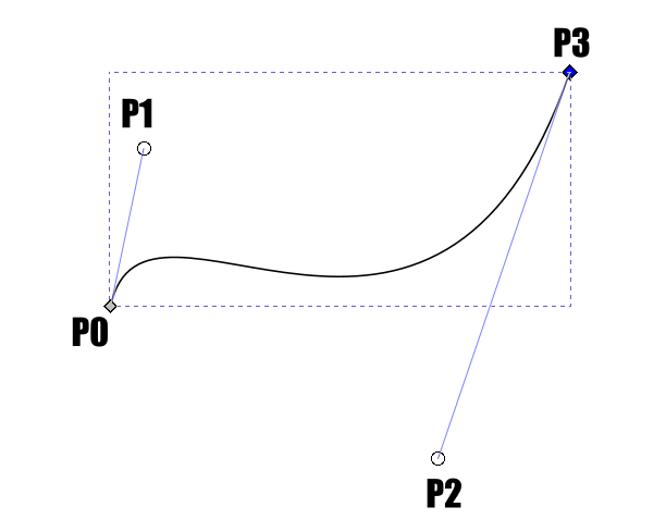
There are broadly two types of curves in Blender. If you create a cylinder, sphere or circle you will get an approximate curve that is made up of numerous straight lines. I am not interested in that here. You can also do real curves, of which there are various types, and that is the subject of this post. Spline This is a generic term for a curve. Splines in design pre-date computers; they were originally strips of wood that were constrained by pegs, and naturally assuming the least strained curve. Historically, they were used to design boats and aircraft. In the context of computers, a spline is a series of joined curves. The points where they join are called knots, and the points you move to change a individual curve are called control points. Bezier Curve A Bezier curve  is defined by a number of control points, the first and last being the start and end of the curve. If there are no further points, you have a straight line. In all the applications I have seen, the Bezier curve h...
Experimenting with supports

Image
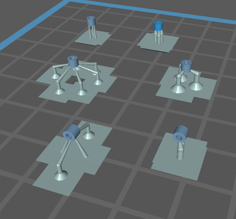
 I need some tiny parts - cylinders 2.4 mm across, 2 mm high, with a hole in the middle. They need to be pretty accurate - bogies will rotate on them and a "top hat" pin needs to go through the hole. What is the best way to support them for printing? Small parts need a relatively large number of supports - I have already established that - but that has a necessary loos of fidelity. My first attempt had them vertical, with three medium supports directly under it. Out of eight prints, two were useable - the rest the holes did not form, and the bases were rough on all of them, though sanding did resolve that. So here are six trials. On the left, three using light supports, on the right medium supports. In the top row three supports directly under the part, in the middle row I have the supports out at the sides; this allows space for more light supports - I am pretty sure three medium is enough. On the bottom row, I have tried having the cylinder horizontal. I did three of each, ...

The USB Stick

An integral part of the print process is transferring the .ctb file from your computer to the printer. The printer comes with an unbranded USB stick to do that. It is just 4 Gb, and formatted with FAT32. Comments I have seen on-line suggest the stick is very unreliable. After ten months of not-very-frequent use I have had my computer not recognise it a handful of times, and the printer not recognise it just once, and each time taking it out and putting it back in fixed it, but then the computer said it needed formatting - clearly time to chuck it! However, it does seem to be a weak link that is readily resolved, so I purchased a new one; a SanDisk with a massive 32 Gb. As bought, it was formatted to FAT 32, and working fine without me having to prepare it in any way. In fact, it is better to have two. One reason is if one fails, you can still print. But it is more convenient to swap between them, having one on your computer and one on the printer. When you have a new print job, just sw...

Worcester Viaduct

Image
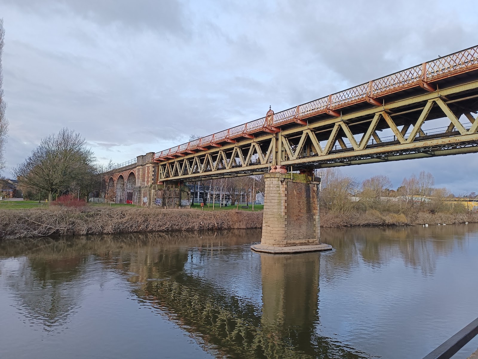
Worcester has a very impressive viaduct that takes the railway across the valley with the River Severn. It was originally opened in 1859, though the two-span girder section crossing the river was built in 1905, and replaced three brick arches - or two iron arches according to some sources. I am inclined to believe the latter, as there was a picture, though it was rather indistinct. The viaduct extends some distance into Worcester, and as-built originally comprised 65 arches. Or 68, as other sources state - it may depend on how you are counting it. Several have numbers, and there is a single arch east of the station where it crossed the A38 (and I did not see) with a "68" on it, indicating that according to some counting there must be 68, but perhaps there are two others like this that purists do not count. Once past Foregate Station, there is an iron bridge over A38; I am not sure if this is original, or another later replacement, but I guess original. The station entrance is...

Geometry Nodes

Image
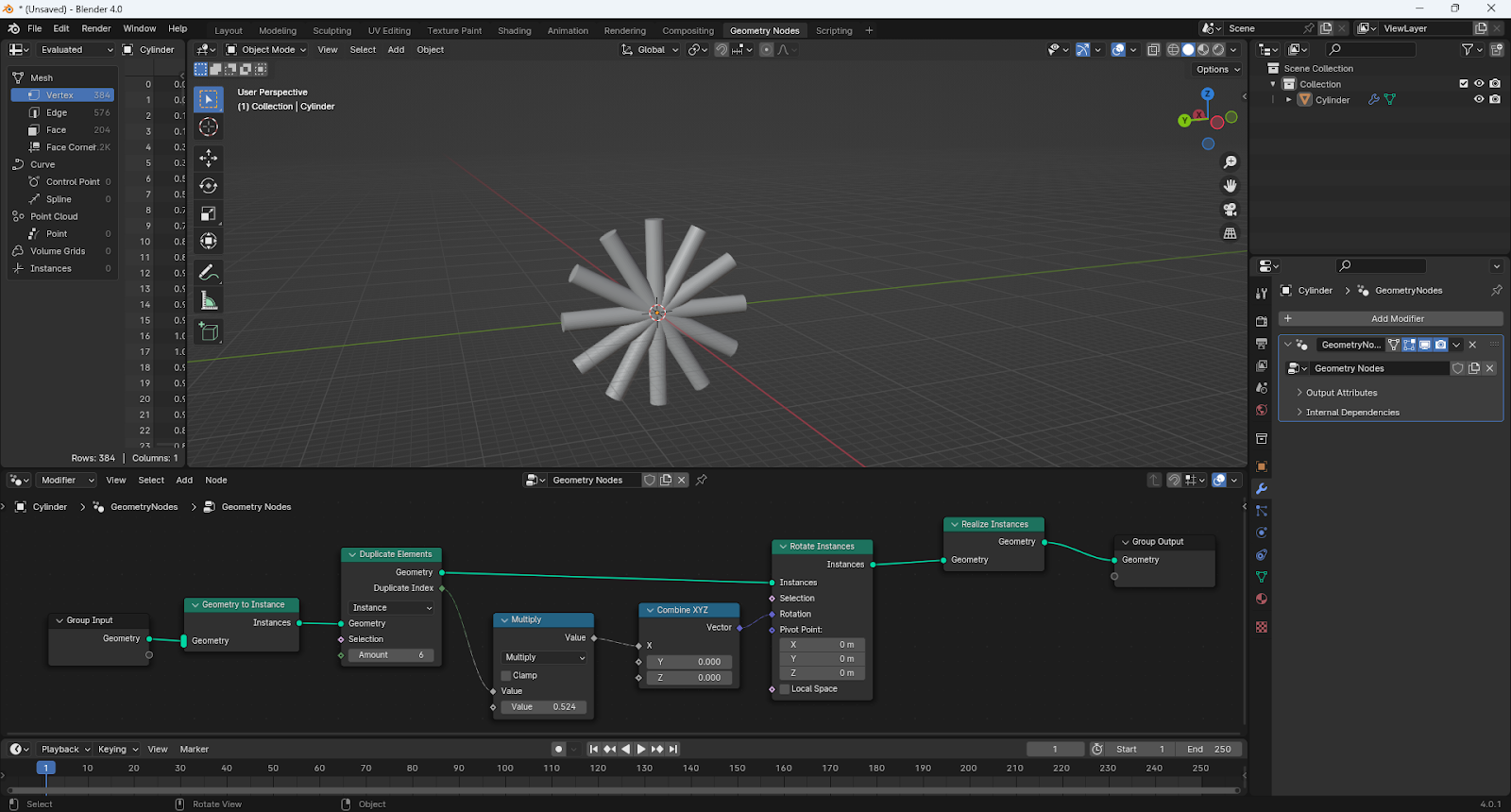
Geometry nodes are kind of like macros; bits of code that you create graphically to do some operation on an object. They work like modifiers, and appear in the Modifiers section of the Properties editor. They also get their own display tab. If you go into it, it looks something like this: The bit at the bottom is the nodes. You can think of them as passing your object through a pipeline, from Group Input at the left to Group Output at the right, following the solid white line. At various points it might need to get another value, so when it gets to that point it backtracks - in the image above along the purple line - gets the value it needs, applies and moves to the next step. Rotation This example is creating duplicates of a cylinder and rotating each duplicate. There are a lot of different node types, and knowing which to use is quite the art. And not one I have! But we can go through this and learn what we can. To add a node, I think the best way is to press [SHFT]-A, and start to...

Bogie Tankers

Image
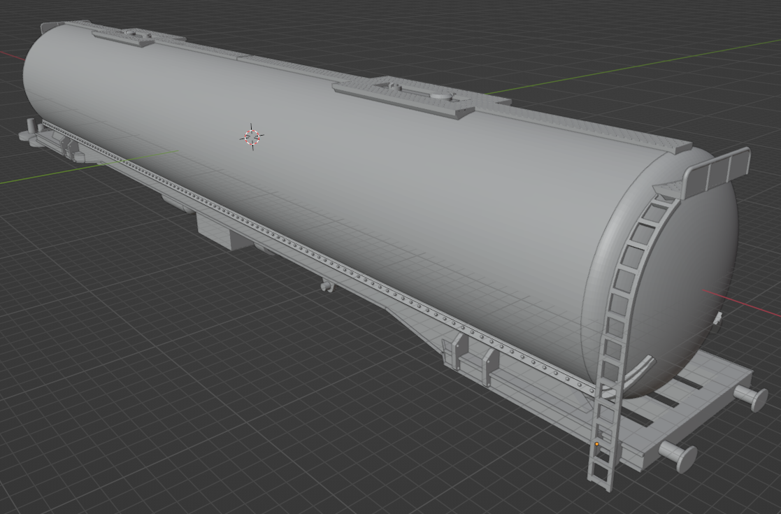
 Based on the ammonia wagon, but adapted to represent a liquid-carrying wagon. And a lagged version. I did the former for a friend, and still waiting to see the result. The lagged version is here: If you zoom in enough, you can see the rivets. I printed eight, and all were missing the bogie pivot at one end, and I am not sure why. It has to be an issue in the design, but I cannot see a problem. I printed out new pivots and glued them on, but now the wheels are rubbing the body, so some further adjustment is required. But they look great! The wet effect where the tar has run down the sides was done using Warhammer paint "Ardcoat".

Stechford footbridge

Image
 I came across this in a book, Bridges for Modellers , by LV Wood, and in fact the side elevation is on the front cover. Stechford is in east Birmingham, and the bridge was built when the line was electrified in 1965. Looks like it has now been replaced by a bridge with lifts. The bridge is concrete, but has "exposed aggregate feature panels", which make for an interesting model. I used geometry nodes to get the effect. The first draft turned out to be too fine, and the effect was hardly noticeable when printed; I think the above gets it just right. This image is from Wiki. I chose not to include the lighting, as it would be so delicate.