Geometry Nodes
Geometry nodes are kind of like macros; bits of code that you create graphically to do some operation on an object.
They work like modifiers, and appear in the Modifiers section of the Properties editor. They also get their own display tab. If you go into it, it looks something like this:
The bit at the bottom is the nodes.
You can think of them as passing your object through a pipeline, from Group Input at the left to Group Output at the right, following the solid white line. At various points it might need to get another value, so when it gets to that point it backtracks - in the image above along the purple line - gets the value it needs, applies and moves to the next step.
Rotation
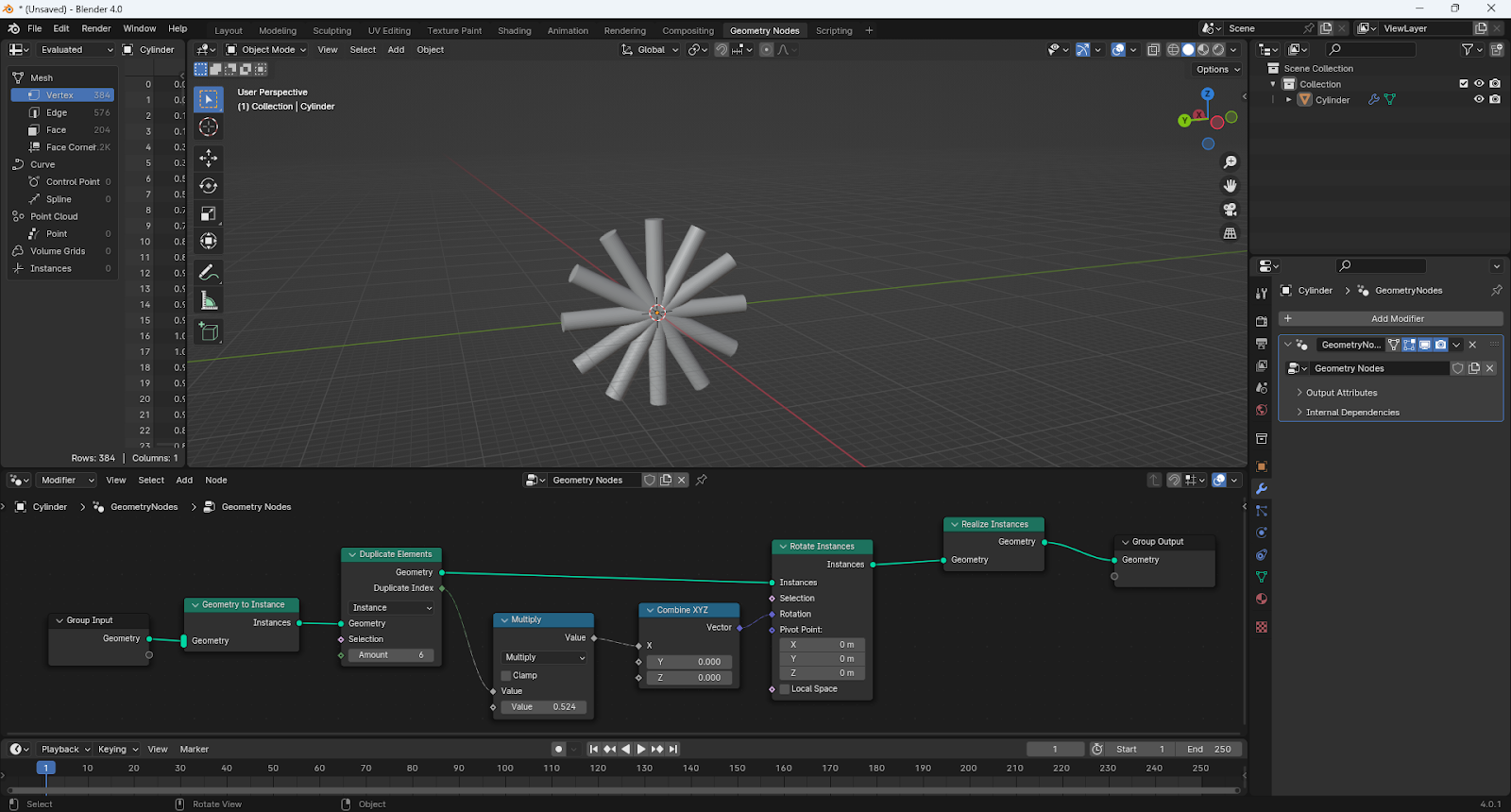
This example is creating duplicates of a cylinder and rotating each duplicate.
There are a lot of different node types, and knowing which to use is quite the art. And not one I have! But we can go through this and learn what we can. To add a node, I think the best way is to press [SHFT]-A, and start to type the name.
The first step converts the Geometry to Instance. I do not know why that is required, but instances are like shadow copies - they are much faster to process.
The next step is Duplicate Elements, which does what it says on the tin. Note that it is set to "Instances", and they might be why we had to convert to instances previously. It defaults to "Points"; if you just see nodes with no edges of faces, you have to change this! We also say how many we want.
There is an extra output here - "Duplicate Index". This is going to give us a number, 0 for the first instance, 1 for the second and up to 5 for the last. This feeds into the next bit.
The Multiply node does nothing with the geometry, it just uses the index number. Note that the node is actually called Math, and is under Utilities; you can select it to do whatever operation you want. I want it to give the angle for the duplicate. Nodes use radians rather than degrees (except when they don't), and there are 2π radians in a full circle. I want one twelfth of that, about 0.524, but you can type in "pi/6" and Blender will understand it.
The output from that goes into a Combine XYZ node, which generates a vector from the calculated value.
That vector, plus the geometry instance from earlier, go into Rotate Instances, to give us a rotated instance.
Finally we need to Realize Instances to ensure the generated instances actually get exported in the STL file.
Further Rotation

This is a more advanced version that could be used for arranging bolts in a circle. The bolt object is placed at the centre of said circle.
There is a Translate Instances node that moves the object out from the centre, before rotating it about the original centre of the object. The distance will be how far the bolts are from the centre (as per the object scaling).
There is also a second Rotate Instances node, with a random input, so each bolt is at a random angle. Note that "local space" is ticked, as this time we are rotating about the object's new origin.
Surface Effect
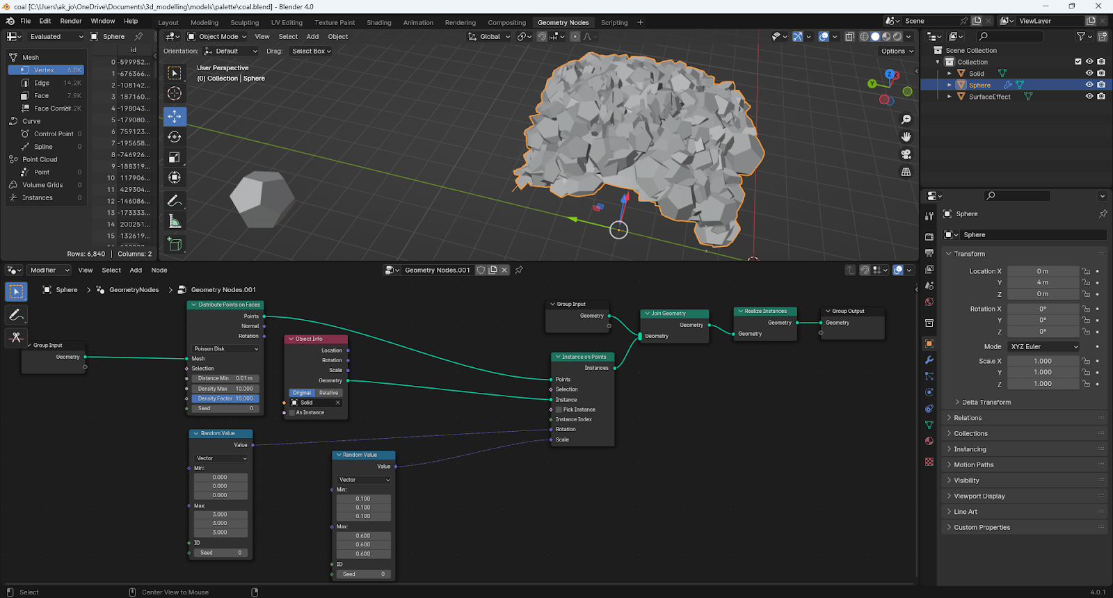
Here is another example, creating a pile of coal. This involves two different objects! The primary object (i.e., the one with the geometry nodes modifier on it) is a curved plane that forms the shape of the pile. Lumps of coal are generated from the dodecahedron.
So the curved surface is the input. It goes to the Distribute Points on Faces node, which creates a number of points randomly across it. There are various options to control how that is done. "Poisson Disk" allows you to ensure none are too close together.
The next step is Instances on Points, which generates a geometry instance on each of those points. This needs some extra information. Firstly it needs the dodecahedron, which we add using an Object Info node. you can use the eye dropper to select the object from the viewport.
Then we have two random vectors, one controlling rotation and one controlling scale. What this all means is that each point on the surface will be converted to an instance of the dodecahedron, rotated and scaled randomly.
Distribute Points on Faces actually converts the object to points, rather than adding the points to it, so the next step combines our lumps of coal with the original surface, using Join Geometry.
Finally, as before, we need to Realize Instances.
I have used the same technique on this footbridge. It does create a lot of complex geometry, and MS 3D Builder took well over an hour to repair it - but it did do.

There are some amazing examples of what you can do with geometry nodes here, though may not be applicable to what I want.


Comments
Post a Comment