Curves
There are broadly two types of curves in Blender. If you create a cylinder, sphere or circle you will get an approximate curve that is made up of numerous straight lines. I am not interested in that here.
You can also do real curves, of which there are various types, and that is the subject of this post.
Spline
This is a generic term for a curve. Splines in design pre-date computers; they were originally strips of wood that were constrained by pegs, and naturally assuming the least strained curve. Historically, they were used to design boats and aircraft.
In the context of computers, a spline is a series of joined curves. The points where they join are called knots, and the points you move to change a individual curve are called control points.
Bezier Curve
A Bezier curve is defined by a number of control points, the first and last being the start and end of the curve. If there are no further points, you have a straight line.
In all the applications I have seen, the Bezier curve has two intermediate control points (cubic Bezier curves), one linked to each end. Call them P0, P1, P2, P3. The curve starts from P0, heading initially towards P1, and finishes at P3, coming from the direction of P2.
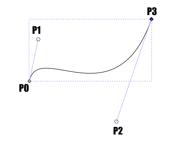
Mathematically, a Bezier curve is a function of t, as t varies from zero to one.
P(t) = P0.(t-1)^3 + 3P1.t.(t-1)^2 + 3P2.t^2.(t-1) + P3.t^3
You can see why it is a cubic curve! When t = 0, P(t) = P0. When t = 1, P(t) = P3.
Bezier Spline
A spline could be composed of a series of Bezier curves.
The relationship between adjacent intermediate points determines the continuity. Say we have one curve P0, P1, P2, P3 and a second P0', P1', P2', P3'. To be a spline, P3 must be equal to P0'; i.e., the point where the second starts is where the first ends (the knot).
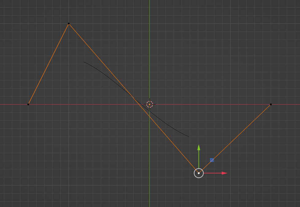
If P2, P3/P0' and P1' lie on a straight line you will have a smooth transition from one curve to the other - and this is the default for Bezier curves in Blender. This is called tangent continuity, as seen below.

If in addition the distance from P2 to P3/P0' is equal to the distance to P1' we have velocity continuity (presumably because if the spline is a path something is travelling along its velocity will change smoothly).
Bezier In Blender
After adding a Bezier curve, the first thing I do is straighten it out; go into edit mode and move the offending control point by 0.5!
You can extend a curve by extruding the end with "E", and I usually work with them by extending a point, setting that to get the curve right, then extend again. You can insert a knot between existing knots using the standard subdivide option (via the right-click menu). To join to ends together, select both and press "F".
You can set each knot of a Bezier curve between the three types by selecting the point and pressing "V".

Blender allows you to add a Bezier circle. It is actually only an approximation, but hard to imagine anyone noticing.
B-Spline
A Bezier spline is a type of basis spline, more commonly called a B-spline.
A Bezier spline requires that each curve is the same length; this is a uniform B-spline. This does not mean each curve is the same length, but rather that something travelling along the spline will take the same time to get from one knot to the next, regardless of how far that is, so not relevant to 3d modelling at all!
NURBS
A non-uniform B-spline does not have that restriction. Furthermore, a rational B-spline allows us to give control points different weighting. These together give us a non-uniform rational b-spline, or NURBS.
By default, a Blender NURBS does not go to the ends. Curves have their own tab in the properties pane, and in there, towards the bottom, is Active Spline. You will see an "Endpoint" option, which will make the curve go through the end points. You can also make it cyclic (join the ends together)
It may be that the control points on a NURBS curve are the intermediate control points for each Bezier curve, with the points of the knots omitted (or interpolated) except at the ends?
There is also a NURBS circle, and this is an exact circle.
Bezier or NURBS?
So which do you use? If you have straight sections in your curve, use Bezier; that is the only one with sufficient control to do that. In fact, if you need precise control, Bezier is the best option. On the other hand, for something like a hose or rope or cable, a NURBS is probably better, as it is easier to move into more natural flows.
Using Curves
A curve has no natural thickness so is no use as is, but we can either give them thickness or use them to deform something else using the "Curve" modifier.
The image below shows a NURBS given a bevel. Find this on the geometry section of the Curves property pane. By default you just get a round cross-section - and this is usually what you want - but you can use another object to define the cross-section or do a custom one as shown here.
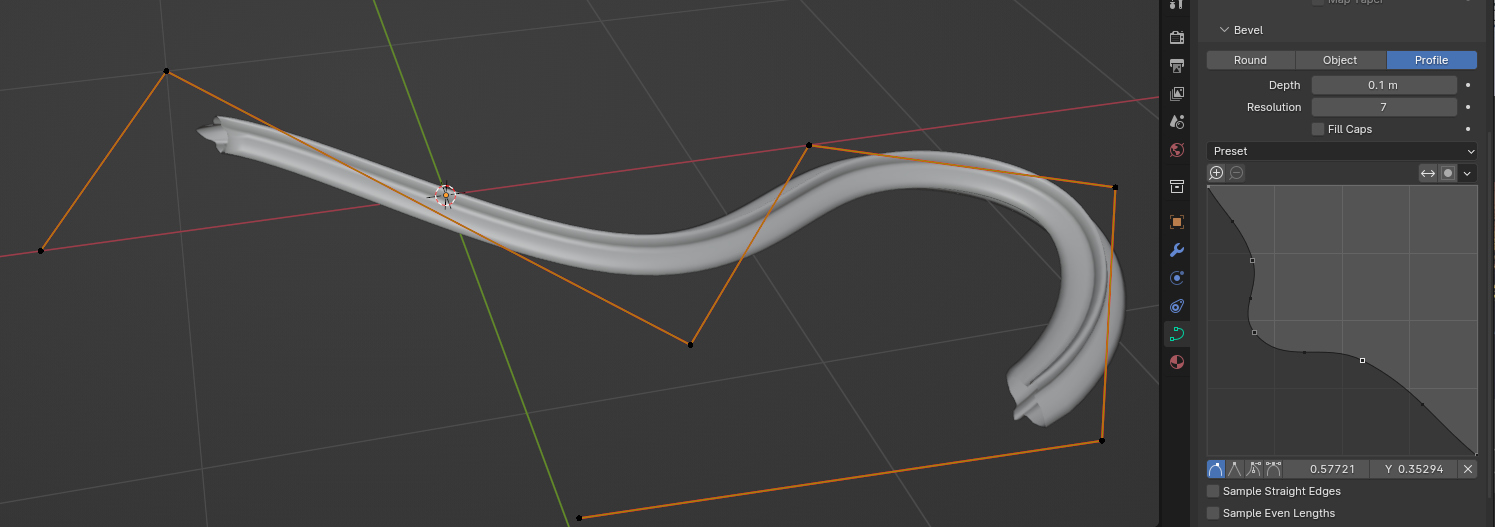
You can see it in a real model here, where the hoses are NURBS with a bevel (the pipes across the top were done using the Spin tool, but in hindsight I should have used a Bezier curve).


Comments
Post a Comment