Posts

Showing posts with the label Feature

Stanley Dock Bridge

Image
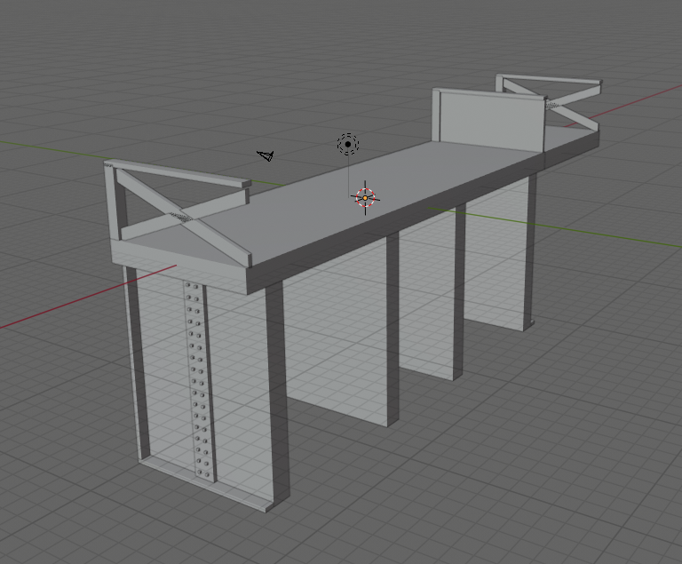
The prototype is discussed here . It is a complex model, but for the most part not technically challenging. The worst part was aligning the pivot with the centre of the arc, and I am not quite sure I got it right. In hindsight I should have done the pivot first... There was also the cog and rack. The cog on the back of the curve is the rack aligned to a curve. There does not seem to be a cog and rack on the prototype, but I felt I would need one to make up for the lack of weight. I printed it in four parts, the two big being the main stationary infrastructure and the lifting the span. The roof and top of the counterweight being the other two. The lifting span was printed upside down. The road deck is card. I designed it hoping it could be motorised, but the lifting span was too wide, and catches on the stationary part. With a bit of effort it could be modified, but that is a job for another day.

Modular footbridge

Image
If you want a simple footbridge that spans two tracks there are lots of options available - I have made three myself. But often the rail is not as simple as that. What if there are three or four tracks? What if the railway is in a cutting? What if there are two tracks going through two platforms, then four tracks in the sidings, and you need to span them all? Just use this modular footbridge! NOTE: This is available to download on Cults3d , for € 2.50. Here you can see a longer span on the left to stretch a bit further over the platforms, while the centre and right spans are designed to go across two tracks, but not platforms. The two sets of steps to the left are short, as they go down to the platform level - and one allows a bridge either side, the other on just the one side. The steps on the right go all the way to track level. There is also a pier. Here is the full set of parts that I have so far. A: platform level steps, end on. B: platform level steps, turning right (but coul...

The ELR Bridge over the Ribble - The Model

Image
The prototype is discussed elsewhere . This has been a long time in development, and bits were printed some time ago. It is now coming together! Due to limited space, there is only one pier, and the height is reduced to fit. The abutments and pier are decorative - they are not intended to take weight. Instead, tracks will be supported by two aluminium U tubes, held up be wood at each end. The deck is made up of repeating sections that look like this in Blender: Eight are joined together to form one section for printing, and four of these are required. Each section is slid over the aluminium U tubes. At each end, there is an additional unit, plus an extension to the end of the U tube - the wooden supports go under that. The pier and abutments were printed in parts - an upper section and a lower section. The steps and curve of the arch were further parts. The image shows them after painting. The pier will be stood in the river, so is longer, which is why the section slopes! And here it i...

A Modular Viaduct (part 2)

Image
I am doing a demo at the local N Gauge Society members day on Sunday, and will be assembling my viaduct to display it. To get it ready, I have been busy painting the last two days, so more photos. I painted iron arch bridge with bright colours, and it turned out well, I think, though my painting skills are not great. The plate girder bridge I did in plain grey. Similarly the lattice bridge. I am  not so happy with his one; the proportions seem out somehow. An extended brick arch. And some filled in arches, with businesses. Again, very pleased with how these turned out.

A Modular Viaduct (part 1)

Image
This is a work in progress, but I wanted to show what I have so far. The basic concept here is that railway viaducts are often made up of different parts. Obviously you can have a plain arch, but if there is a longer distance to span, one section could be iron or steel, or just a different, extended arch. Arches are often filled in, and sometimes rented out to business use. Viaducts are, by there nature, big, so a 3d print would have to be done in sections, and given that it then becomes attractive to design sections that could be put together in different configurations. What I have come up with is a set of joiners and sections. Joiners are all the same; the sections are varied. This shows the basic concept. You can see the first and fourth sections are plain arches, the second and third are businesses, and the fifth is filled in. The sections still need parapets added. The join is very simple, just an angled section that goes inside the joiner. The plan is to have basswood strips ove...

Stechford footbridge

Image
 I came across this in a book, Bridges for Modellers , by LV Wood, and in fact the side elevation is on the front cover. Stechford is in east Birmingham, and the bridge was built when the line was electrified in 1965. Looks like it has now been replaced by a bridge with lifts. The bridge is concrete, but has "exposed aggregate feature panels", which make for an interesting model. I used geometry nodes to get the effect. The first draft turned out to be too fine, and the effect was hardly noticeable when printed; I think the above gets it just right. This image is from Wiki. I chose not to include the lighting, as it would be so delicate.

Tunnel Portals

Image
Three double-track tunnel portals... The first is based on a tunnel portal at Shotlock on the Settle-Carlisle line. Tunnels support a lot of weight over them, and that weight needs to be distributed down the sides of the tunnel. To do that, larger tunnels are elliptical, with the major axis vertical rather than horizontal. Unfortunately, a lot of models of tunnel portals are almost flat at the top - see here for example. That is just not going to hold the roof up. The reason models are like that, of course, is that it takes up less height. The more realistic approach is to have two single-track tunnel portals. This, however, uses more width. The second portal takes that approach, and, if I am honest, probably has the two bores too close together. There is a lot of weight being supported by a fairly thin wall of rock and brick. The design is free-lance. It is brick, with three courses of arches, though five may have been more prototypical. The third design breaks the principle I discus...

Canal bridge

Image
There are numerous bridges of this design along the Lancaster Canal, and I assume across the country. I am particular pleased with how well defined the brickwork is. Image of the prototype for reference.

Copley Hill plate girder bridge

Image
 My second decent print is a bridge (the bus is not 3d printed). This is based on a prototype at Copley Hill in Leeds. I managed to print it under-scale - it should be 50% bigger. Aside from that, I am pleased with the result. I am still having issues with parts dropping off. Only two of the four wings printed and there should be sections to go between the tracks that also failed. I am wondering if the zero is too low?