A Modular Viaduct (part 1)
This is a work in progress, but I wanted to show what I have so far.
The basic concept here is that railway viaducts are often made up of different parts. Obviously you can have a plain arch, but if there is a longer distance to span, one section could be iron or steel, or just a different, extended arch. Arches are often filled in, and sometimes rented out to business use.
Viaducts are, by there nature, big, so a 3d print would have to be done in sections, and given that it then becomes attractive to design sections that could be put together in different configurations.
What I have come up with is a set of joiners and sections. Joiners are all the same; the sections are varied. This shows the basic concept.

You can see the first and fourth sections are plain arches, the second and third are businesses, and the fifth is filled in. The sections still need parapets added.
The join is very simple, just an angled section that goes inside the joiner.

The plan is to have basswood strips over the top; I have some that is 2 mm thick and 50 mm wide. I have done the sections so they are 92 mm wide at the front, but 94 mm at the back, so there is a very gentle curve.
For longer span bridges, I have incorporated the joiners into the bridge. And just to add interest (and yes, show off), I have done them on a skew. The plate girder bridge is skewed by 11 degrees.

The iron arch is skewed by 30 degrees, which does enhance it significantly in my view.

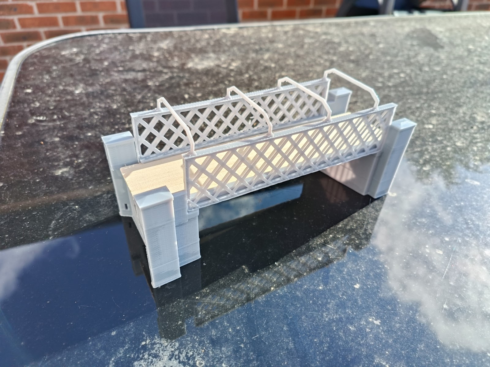
Here is a lattice bridge, skewed 11 degrees the other way. The lattices are made up of two parts, rather than solid, as per the prototype, but rarely modelled.


Comments
Post a Comment