Posts

Showing posts from January, 2024

Geometry Nodes

Image
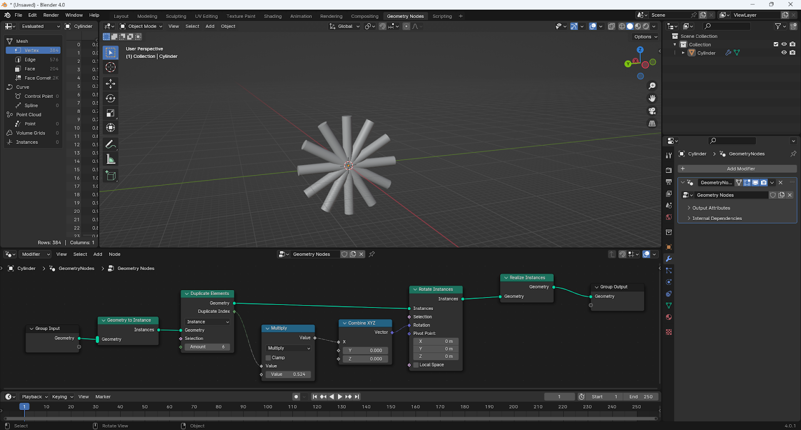
Geometry nodes are kind of like macros; bits of code that you create graphically to do some operation on an object. They work like modifiers, and appear in the Modifiers section of the Properties editor. They also get their own display tab. If you go into it, it looks something like this: The bit at the bottom is the nodes. You can think of them as passing your object through a pipeline, from Group Input at the left to Group Output at the right, following the solid white line. At various points it might need to get another value, so when it gets to that point it backtracks - in the image above along the purple line - gets the value it needs, applies and moves to the next step. Rotation This example is creating duplicates of a cylinder and rotating each duplicate. There are a lot of different node types, and knowing which to use is quite the art. And not one I have! But we can go through this and learn what we can. To add a node, I think the best way is to press [SHFT]-A, and start to...
Bogie Tankers

Image
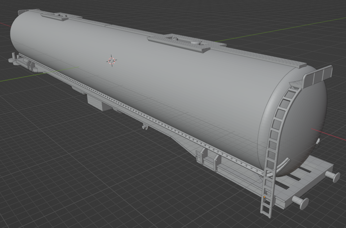
 Based on the ammonia wagon, but adapted to represent a liquid-carrying wagon. And a lagged version. I did the former for a friend, and still waiting to see the result. The lagged version is here: If you zoom in enough, you can see the rivets. I printed eight, and all were missing the bogie pivot at one end, and I am not sure why. It has to be an issue in the design, but I cannot see a problem. I printed out new pivots and glued them on, but now the wheels are rubbing the body, so some further adjustment is required. But they look great! The wet effect where the tar has run down the sides was done using Warhammer paint "Ardcoat".

Stechford footbridge

Image
 I came across this in a book, Bridges for Modellers , by LV Wood, and in fact the side elevation is on the front cover. Stechford is in east Birmingham, and the bridge was built when the line was electrified in 1965. Looks like it has now been replaced by a bridge with lifts. The bridge is concrete, but has "exposed aggregate feature panels", which make for an interesting model. I used geometry nodes to get the effect. The first draft turned out to be too fine, and the effect was hardly noticeable when printed; I think the above gets it just right. This image is from Wiki. I chose not to include the lighting, as it would be so delicate.

Tunnel Portals

Image
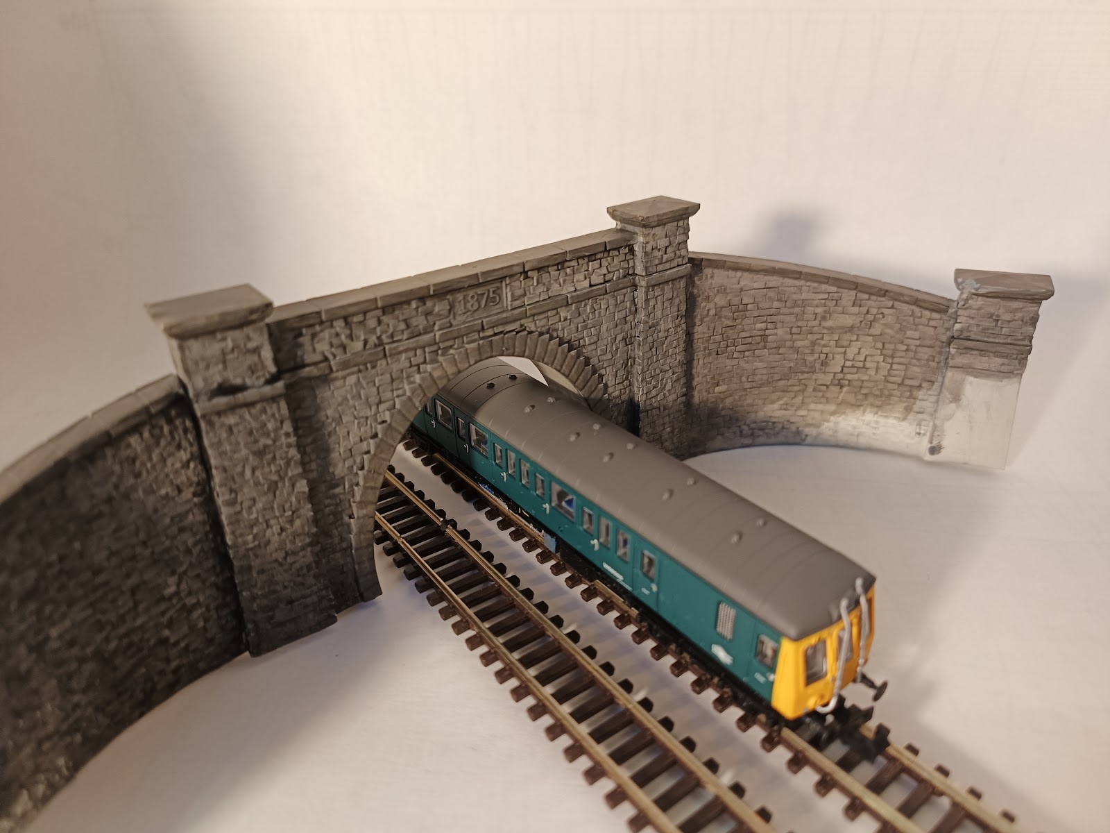
Three double-track tunnel portals... The first is based on a tunnel portal at Shotlock on the Settle-Carlisle line. Tunnels support a lot of weight over them, and that weight needs to be distributed down the sides of the tunnel. To do that, larger tunnels are elliptical, with the major axis vertical rather than horizontal. Unfortunately, a lot of models of tunnel portals are almost flat at the top - see here for example. That is just not going to hold the roof up. The reason models are like that, of course, is that it takes up less height. The more realistic approach is to have two single-track tunnel portals. This, however, uses more width. The second portal takes that approach, and, if I am honest, probably has the two bores too close together. There is a lot of weight being supported by a fairly thin wall of rock and brick. The design is free-lance. It is brick, with three courses of arches, though five may have been more prototypical. The third design breaks the principle I discus...