Circles of Steel and Wood
I have recently made some wagon loads, three of them based on wrapping steel into circles, which poses some interesting challenges for the 3d modeller.
There is an article about curves here that will serve as a background to the modelling.
https://three-d-for-railways.blogspot.com/2024/02/curves.html
I would guess that at one time iron and steel was the second big industry for railways (after coal), and it was the ready availability of both coal and iron ore that made Britain so successful in the industrial revolution.
An issue with transporting steel is how do you move it? Coal is in lumps, making transport relatively easy. Steel parts can be huge. It appears it was generally transported between sites in coils and in wire bails. I would guess wire bails are used for making items that are that kind of shape, like thinner wire, nails, etc. Steel coils would be unwound to make refrigerators, ships, or whatever.
That said, the first item I made is a cable drum. In fact, it is a set of cable drums, as would be seen on electrification wagons. One drum is larger, I assume because the wire is thicker diameter, and the wagon I saw had three, so was probably for the lines from Euston to Crewe in the sixties, which had an extra auxiliary wire. The long beams on the base were to fill the space on the wagon.
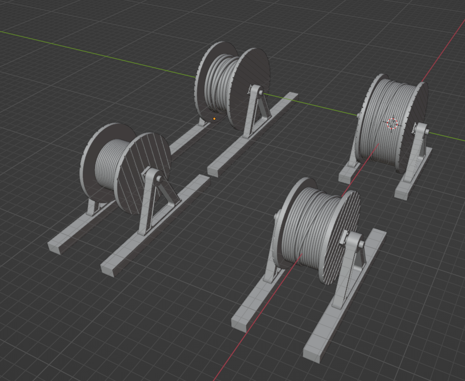
The drums are just cylinders - that is the easy part. The neatly coiled cables are a circle that was extruded using the "Spin" tool in edit mode, and then an Array modifier used to create many of them. The outer wires, the ones that are not neatly lined up, are NURBS curves that are given a suitable bevel. Not sure how apparent that is in the model.

The second item is a bale of wire. It was made in a similar fashion, just without the drum.


Of the four items described here, I think they turned out best.
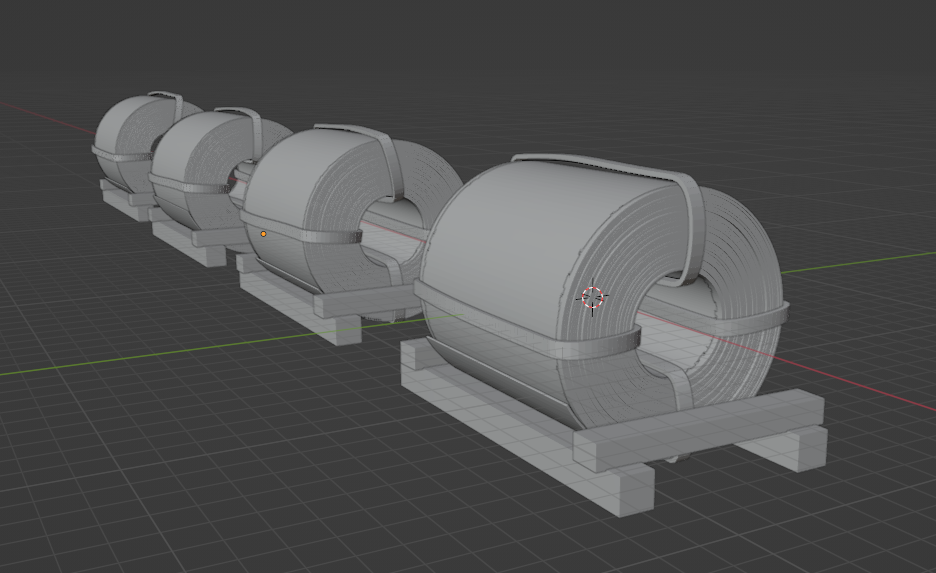
The ends are made from a jagged line that is that extruded with the "Spin" tool. The bindings are as before.
Some of them have marks where there were supports on the binding, which is not ideal, but not too obvious.

I experimented with giving the logs physics, and using animation to get them to fall naturally, but in the end it was better to adjust them by hand. I created a box the right size, and arranged them with in it. A further box in the centre of each bundle, and shaped appropriately, keeps them all together.

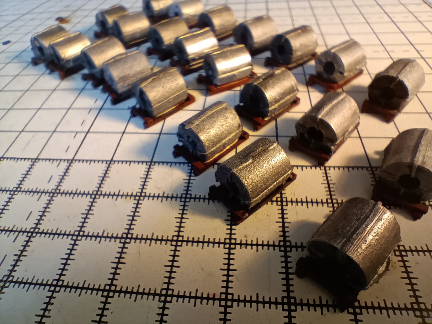
This was for a friend. Here are some he printed and painted, and in a wagon. He needs fifty or so for his train...

Comments
Post a Comment